

Introduction
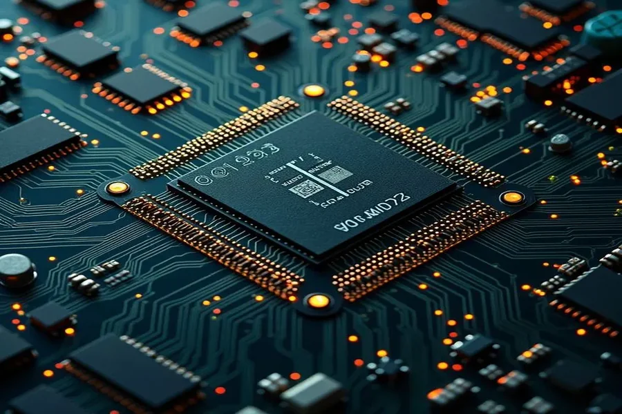
Every electronic device you use — from your smartphone and TV to industrial machines and medical equipment — runs on printed circuit boards (PCBs). These boards are the backbone of modern electronics, acting as the central hub where all electrical signals flow. But when a circuit board malfunctions or needs modification, the first challenge is understanding what each tiny part on the board actually does.
This process is known as identification of circuit board components. It’s a critical skill for students, electronics hobbyists, engineers, and repair professionals alike. Without this ability, troubleshooting, repairing, or designing circuits would be nearly impossible.
In this guide, we’ll break down the step-by-step process of identifying PCB components, explore the most common parts with clear explanations and visuals, compare surface-mount vs through-hole parts, and even share practical tips, safety guidelines, and tools you can use. By the end, you’ll be confident in reading and recognizing almost any component you encounter.
What is a Printed Circuit Board (PCB)?
A printed circuit board is a flat, layered board that mechanically supports and electrically connects electronic components using copper traces (thin conductive pathways).
Key elements of a PCB:
-
Substrate/Base Layer: Usually fiberglass (FR4) that gives the board strength.
-
Copper Layer: Thin conductive sheets that form electrical pathways.
-
Solder Mask: The green (sometimes red, blue, or black) coating that prevents short circuits and oxidation.
-
Silkscreen: White labeling layer that shows component outlines, part numbers, and reference designators.
Think of a PCB as the “roadmap” of an electronic device: the copper traces are roads, components are buildings, and together they form a working city.
Why Identification of Circuit Board Components is Important
Learning how to identify PCB components has both practical and professional benefits:
-
For hobbyists & students: Helps in building projects, repairing simple gadgets, and understanding electronics deeply.
-
For technicians & repair engineers: Essential for diagnosing faults, replacing defective components, and ensuring machines run smoothly.
-
For reverse engineering & prototyping: Engineers often analyze existing PCBs to improve designs or replicate functionality.
-
For sourcing replacements: Correctly identifying parts ensures you order the right substitutes when originals are discontinued or burned out.
In short, without mastering identification circuit board components, you’re left guessing — and guessing in electronics usually leads to more damage than repair.
Step-by-Step Guide to Identification of Circuit Board Components
Here’s a simple process you can follow whenever you face an unfamiliar circuit board:
Step 1: Observe the Board Function
-
Look for labels, model numbers, or manufacturer information.
-
Try to understand the purpose of the board (e.g., power supply, motor controller, audio amplifier). Knowing the function narrows down what components to expect.
Step 2: Check Reference Designators
On most PCBs, every part is marked with a reference designator printed in silkscreen:
-
R = Resistor
-
C = Capacitor
-
D = Diode
-
Q = Transistor
-
U or IC = Integrated Circuit
-
L = Inductor
-
K = Relay
-
J or P = Connector or Port
-
F = Fuse
These designators are your first clue. Even if you don’t recognize the part visually, the letter tells you what category it belongs to.
Step 3: Match Physical Appearance
Use visual cues:
-
Cylindrical shapes → Capacitors
-
Tiny black chips with legs → ICs
-
Spiral coil of wire → Inductor
-
Glass body with stripe → Diode
Step 4: Confirm with Datasheets or Manuals
If you find a part number (printed on the component), search it online with “datasheet.” This gives exact specifications. Many datasheets include package drawings that confirm identification.
Common PCB Components and How to Identify Them
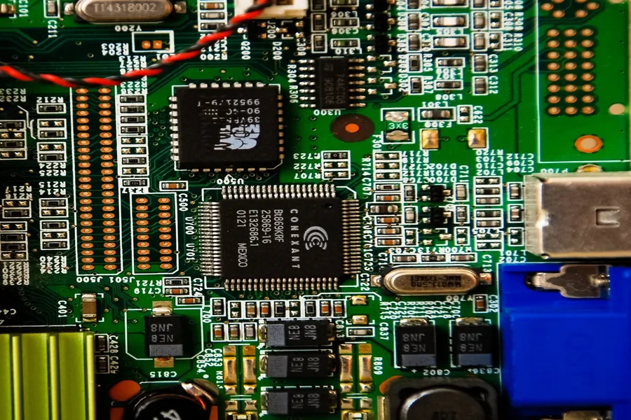
Here’s a detailed list of the most frequent PCB components, organized by category.
Quick Reference Table
| Component | Designator | Function | How to Identify | Common Packages |
|---|---|---|---|---|
| Resistor | R | Limits current, sets voltage | Small cylinders (through-hole) or tiny rectangular blocks with numbers (SMD) | Axial, SMD 0805/0603 |
| Capacitor | C | Stores & releases energy, filters signals | Cylindrical electrolytic (with polarity mark), disc ceramic, or small SMD blocks | Radial, Axial, SMD |
| Diode | D | Allows current in one direction | Black body with silver/white stripe marking cathode | DO-41, SMD SOD-123 |
| Transistor | Q | Switches or amplifies signals | Three-legged device, often black semicircle (through-hole) or flat SMD | TO-92, SOT-23 |
| IC / Chip | U or IC | Complete circuits inside a package | Black rectangle with many pins | DIP, QFP, BGA |
| Inductor | L | Stores energy in magnetic field, filters noise | Wire coils or ferrite blocks | Toroidal, Axial, SMD |
| Relay | K | Electrically controlled switch | Box-shaped, transparent or solid color | DIP Relay, Cube Relay |
| Fuse | F | Protects circuit from overcurrent | Glass tube with metal ends, or small SMD block | Glass cartridge, SMD fuse |
| Connector | J or P | Provides input/output connection | Pin headers, sockets, edge connectors | Pin header, USB, RJ45 |
| Crystal | Y or X | Provides precise frequency clock | Small metal can, oval or rectangular | HC-49, SMD |
| Transformer | T | Transfers energy between circuits | Wound coils of wire, often larger in power circuits | EI Core, Toroidal |
Passive Components
Resistors (R)
-
Function: Limit current, divide voltages.
-
Identification: Through-hole resistors have colored bands indicating resistance. Surface-mount (SMD) resistors have numeric codes.
-
Example: 220Ω resistor marked with red-red-brown-gold.
Capacitors (C)
-
Function: Store and release energy, filter signals.
-
Types:
-
Electrolytic (cylindrical, polarity marked with stripe).
-
Ceramic (small disc or block, non-polarized).
-
Tantalum (drop-shaped with polarity mark).
-
Inductors (L)
-
Function: Store energy in a magnetic field, filter AC signals, stabilize currents.
-
Identification: Coils of copper wire or block-shaped ferrite cores.
Active Components
Diodes (D)
-
Function: One-way current flow, rectification, signal control.
-
Identification: Black cylindrical body with silver/white band (cathode). LEDs glow when powered.
Transistors (Q)
-
Function: Amplify signals, act as switches.
-
Identification: Three leads (base, collector, emitter). Small semicircle (TO-92) or tiny SOT-23 in SMT.
Integrated Circuits (IC / U)
-
Function: Miniaturized circuits inside a single package.
-
Identification: Black chips with multiple pins. Look for part number (e.g., LM324, 555, ATmega).
-
Packages: DIP (through-hole), SOIC, QFP, BGA (surface mount).
Electromechanical & Support Components
Relays (K)
-
Function: Electrically operated switches.
-
Identification: Boxy shape, often transparent. Label includes coil voltage (e.g., 12VDC).
Connectors (J/P)
-
Function: Connect board to external devices.
-
Examples: USB, HDMI, pin headers, screw terminals.
Transformers (T)
-
Function: Change voltage levels, isolate circuits.
-
Identification: Large wound coils, usually in power supplies.
Crystals & Oscillators (Y/X)
-
Function: Provide precise timing signals.
-
Identification: Small metal cans or rectangular blocks. Common value = 16MHz (microcontrollers).
Fuses & Varistors (F, RV)
-
Function: Protect circuits from surges and overcurrent.
-
Fuses: Break the circuit when current is too high.
-
Varistors: Absorb voltage spikes.
Surface-Mount vs Through-Hole Components
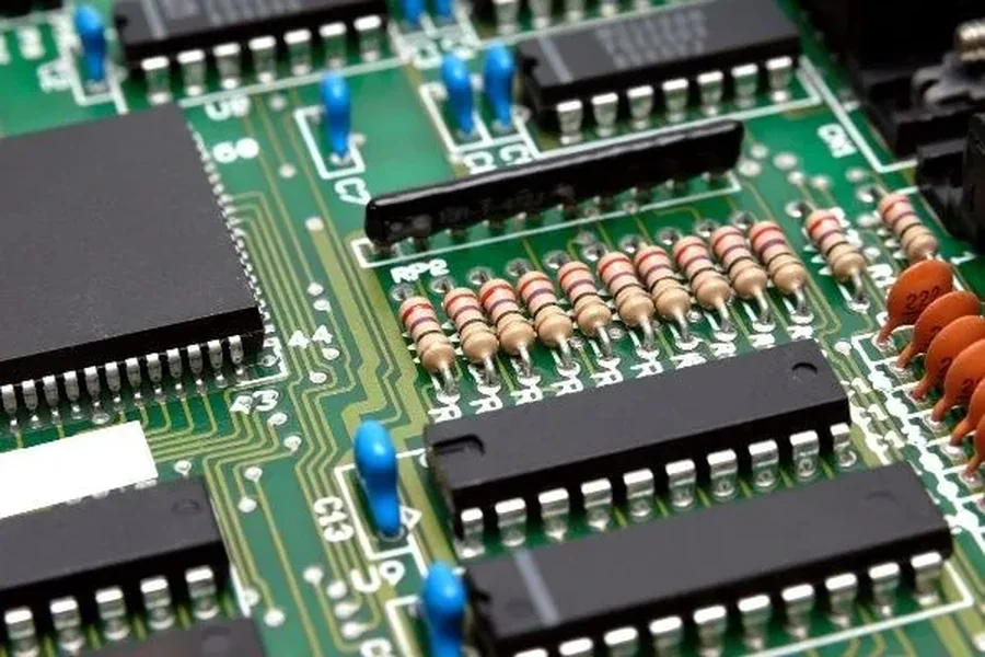
Modern PCBs use surface-mount technology (SMT) because parts are smaller and boards can be packed tightly.
-
Through-Hole (THT): Leads go through holes in the board, easier for beginners.
-
SMT: Mounted directly on copper pads, tiny markings, harder to read without magnification.
Pro Tip: Use a digital microscope for SMT component identification — markings are often just 2–3 tiny letters/numbers.
Tools for Identification
-
Multimeter: Measure resistance, capacitance, diode polarity.
-
Magnifying Glass/Microscope: Essential for SMT boards.
-
Datasheet Search: Enter part number + “datasheet PDF” in Google.
-
Component Testers: Automatic LCR meters or transistor testers.
Challenges in Identification
-
Burned or Damaged Parts: Sometimes only circuit function helps guess the missing component.
-
Obsolete Parts: Many old ICs are discontinued. Equivalent replacements must be found.
-
Non-Standard Markings: Different manufacturers may use unusual symbols.
Safety Considerations
Before touching any PCB:
-
Disconnect power completely.
-
Discharge capacitors (they can hold dangerous voltage even after shutdown).
-
Use ESD protection (anti-static wrist straps, grounded mats).
-
Avoid guessing: Installing the wrong component can destroy a board.
Conclusion
Learning the identification of circuit board components is like learning a new language — at first, it looks confusing, but once you recognize patterns, everything becomes clear. By using reference designators, visual matching, datasheets, and practical tools, you can systematically decode any PCB.
Whether you’re repairing a household gadget, studying electronics, or troubleshooting industrial machinery, this skill is essential. With practice, you’ll not only identify parts but also understand how they interact, making you a more confident and capable technician or engineer.
Read more..